Welcome to the third part of my intelligent hexapod series, where I will delve into the exciting world of simulation and how I connected the physical robot into a simulated environment using ROS2 (Robot Operating System 2). In this article, I will provide clear instructions on the process and discuss key concepts related to ROS2, transforms, and URDF files. (If you missed it, part 1 can be found here, part 2 can be found here)
ROS2 – The Robotic Operating System
ROS2 is a powerful framework consisting of software libraries and tools designed to simplify the development of robots. By sharing common code, developers can focus on creating new algorithms and technologies without starting from scratch. This collaborative approach fosters the growth of the robotics industry and accelerates problem-solving across the community.
Despite its name, ROS2 is not an actual operating system but a collection of libraries and tools on which more complex robotic systems are built. New ROS2 versions, also known as distributions, are released in May each year, and they are designed to run on the latest Long-Term Support (LTS) Ubuntu. While ROS2 can function on other Linux distributions and even on Mac and Windows, it is best supported on Ubuntu, making it an excellent starting point for beginners.
Simulation Setup: Onboard and Offboard Computers
For the hexapod project, I equipped the robot with a small single-board computer – a Samsung S10e running Ubuntu OS. This onboard computer processes raw sensor data into ROS-compatible messages and transmits them over the network. On the other hand, I used a larger, more standard computer (e.g., a mid-range laptop or desktop) as the offboard computer or “base station.” The base station serves multiple purposes: it acts as a “base station” to control the hexapod and as a development machine to run simulations, visualize data, and write code.
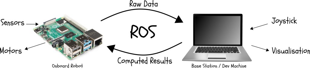
Figure 1: ROS communication diagram
ROS2 Nodes and Topics
A ROS2 system consists of multiple smaller programs, known as nodes, running simultaneously and communicating with each other. Each node performs a specific task as part of the larger system. For example, a node could read data from a sensor, send control signals to a motor, receive input from a joystick, display visualizations, or compute trajectories.
ROS2 nodes communicate with each other using topics and messages. A topic is a named location where one or multiple nodes publish messages, and other nodes, known as subscribers, can subscribe to the topic to receive these messages. This decoupling allows ROS2 systems to run either on a single machine or distribute components across different machines, providing great flexibility.
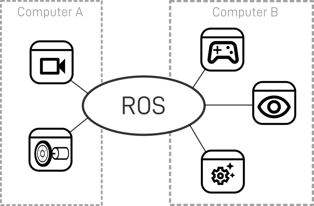
Figure 2: ROS node communication diagram
Choosing the Network Structure
To ensure efficient communication between the onboard and offboard computers, we need a network structure that offers a fast, reliable connection. In my case, I set up a dedicated network with a router receiving its internet connection via Wi-Fi. The router bridges this connection to its own network over both Wi-Fi and Ethernet. The robot connects via Wi-Fi, and the base station connects via Ethernet, ensuring a stable and efficient connection for transmitting ROS2 messages.
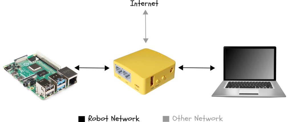
Figure 3: Dedicated network diagram
Unified Robot Description Format (URDF)
When creating a robotic system, it’s essential to have a common location where all software components can access the physical characteristics of the robot. In ROS2, this information is stored in a URDF (Unified Robot Description Format) file.

Figure 4: URDF diagram
The URDF file describes the robot as a tree of links connected by joints. Links represent the physical components of the robot, while joints define how one link moves relative to another, effectively positioning the links in space. This URDF model of the hexapod allows us to visualize and understand its physical structure.
Here is the final URDF model of the hexapod in the RViz2 visualizer software:

Figure 5: Hexapod URDF in RViz2
Conclusion
In this article, I discussed the integration of the physical hexapod robot into a simulation environment using ROS2. We explored ROS2 nodes, topics, and messages, which facilitate seamless communication between components. Additionally, I explained the importance of the URDF file in storing the robot’s physical characteristics for consistency and simplicity.
Throughout the development process, I followed the ROS2 documentation to install and set up my development machine and network protocols. I also created a custom URDF model, which you can find in this repository.
In the upcoming fourth part of this blog series, I will dive deeper into implementing reinforcement learning techniques in the simulation environment to train the hexapod robot virtually. Join me on this exciting journey to achieve true intelligence through the fusion of hardware, software, and advanced learning algorithms.
Stay tuned for more updates and progress in this multi-part series. Don’t forget to subscribe to my newsletter or follow me on LinkedIn for the latest news and insights on this project and other exciting developments.

Leave a reply to Gabriel Giangi Cancel reply